Introduction
I’m subscribed to Dangerous Prototypes’ RSS feed and the constant reminders of the 7400 contest encouraged me to participate this year. I like to think of it as a token of support.
After about half an hour of brainstorming I came up with the idea of a modern musical box. In a few moments I had the core of the machine ready on a paper and I found a suitable tune; Telemann’s Polonaise. It’s simple, short and has only nine different notes.
Usage
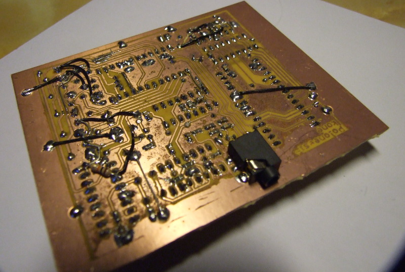
The user plugs the headphone in the 3.5mm socket, turns the power on and presses the button to hear a tune. When the tune is over, the device is automatically reset and the user must press the button again to start over. If the user wishes to hear a different tune altogether, he/she must reprogram the EEPROM…
How it works
Schematic is available in the files section below.
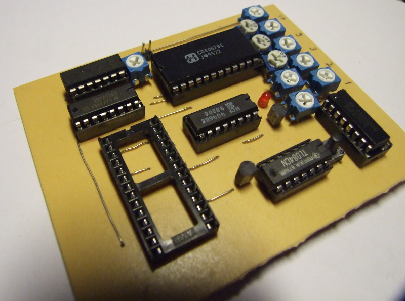
The heart of the circuit is an oscillator constructed of a 4069 NOT gate. It has an adjustable frequency between 4 and 25 Hz. Its output is fed directly to a 4040 counter. The counter is initially in reset state, but it can be enabled by pushing a button. The button push is latched by using a 74F175 D type flip flop. The counter can be reset again by clearing the flip flop (one EEPROM line is dedicated to do this).
The output of the counter is the address input of the EEPROM. To ease the routing I chose to connect only 7 bits, which restricts the amount of notes to 128. It’s note like I want to use this as my everyday MP3 player anyway…
The notes are stored in the EEPROM as numbers, each note has a number between 0 and 9. There are two special “notes”, 0x40 is mute and 0x80 resets the 4040 counter. The four lowest bits – enough to contain the actual notes – are fed to the 4067 analog mux.
The 4067 analog mux chooses the appropriate analog voltage, which are generated using potentiometers wired as voltage dividers, and outputs it to a 4046 PLL. It took some experimenting getting the capacitance and resistance values right. I think I used 100kohm for R1 and 47 kohm for R2, C1 was 220 nF.
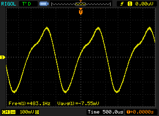
The output of the PLL is AC coupled and then its offset is set between rails. A TL084, which are plentiful in my drawer, is wired as a buffer. Then the signal is low pass filtered to get rid of the nasty-souding square wave harmonics.
Update: This project made it to the second place (with eight other projects).