Playing music on floppy drives is nothing new. The Moppy project has been popular for a few years now, and it was the project that initially caught my attention as well. However, I though that it lacked a certain sense of elegance; FPGA would be much better in generating the waveforms for a bunch of floppy drives at the same time. That project also combines Arduino and Java, both of which are not my favourite things in the world. It also requires a PC.
So I decided to roll an implementation of my own. Last summer I programmed the midi parser on an ARM microcontroller, which sent the data to the FPGA via SPI. The basic VHDL block consists of nothing more than a counter and a lookup table. Eight of these blocks were instantiated in a higher level block and connected to a SPI block which was trivial to program. The MIDI file was hard-coded in the program memory of the microcontroller as a C array. It worked, but it was certainly not satisfied. There’s no need to have anything besides a single FPGA, and the project must have an user interface. Changing the song was too hard in the old version.
In late 2013 I dug up my Terasic DE2 board, which is on loan from my university (thanks TUT!). It’s been a while since my VHDL and SoC classes but I was able to create a QSys system in a short time. Of course, I also had to wrap my HD44780 and waveform generation blocks to use Altera’s Avalon bus. I was really amazed how smoothly everything went.
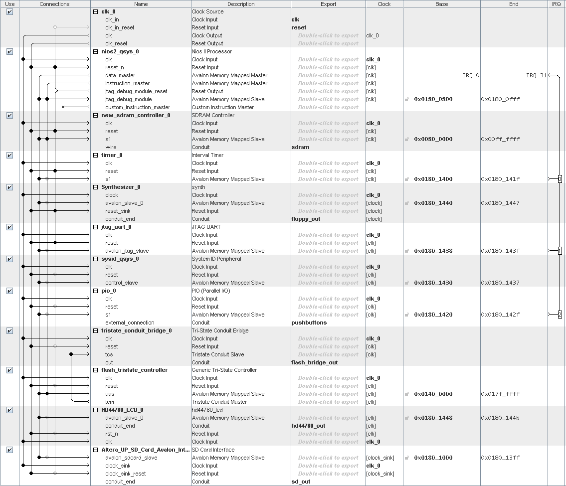
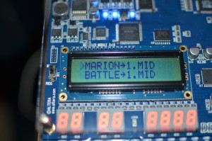
Besides the aforementioned blocks I also used Altera’s SD card IP. It didn’t work with my SDHC card, but an old 128 MB SD card worked fine. I can just save mid files on the SD card and choose the song to play from the HD44780 LCD screen. User input is given using pushbuttons (parallel IO).
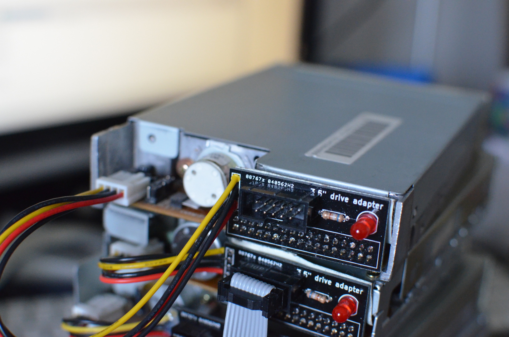
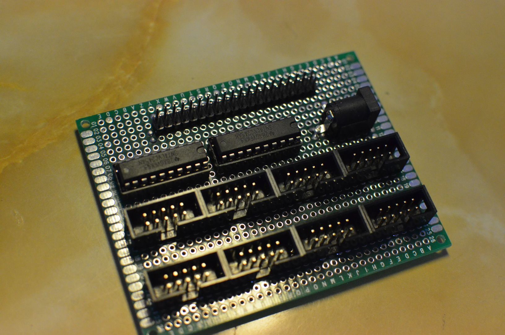
The “music” waveforms are output from the GPIO header and fed to a 74LVC245 buffer. Besides buffering, it also converts the 3.3V signals to 5V. The buffer outputs are directly connected to the floppy drives using 10-pin IDC cables and a simple adapter PCB. The PCB also has an LED indicating power – it also turned out that the current draw of the motors made them flicker in a nice way.
That’s all there was to it really. I think this is as far as I’ll go with this as I think my solution is now elegant enough and I’m sick of hoarding floppy drives. Possible improvements would be combining the channels and floppy drives more intelligently (not all floppy drives are the same and play at the same volume – some sound much more ugly than the others). Sometimes beautiful melodies are hidden beneath the grunting sounds from the other drives.
Here’s a few songs I recorded.