Teardown: Microboards Orbit 3 CD/DVD duplicator

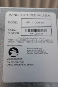
I have been building an automated CD ripping machine for a while now, and during the research phase I stumbled upon some commercial solutions developed by Microboards Technology. The older designs are made by Champion Duplicators Inc. which Microboards acquired in 2000.

Overall view of Microboards Orbit 3.

The loading mechanism used in these devices seems quite novel, so I decided to buy one on eBay for further studies. I could possibly use some of the parts in my own design as well – I have first-hand experience in how tricky mechanisms are to get to work right.

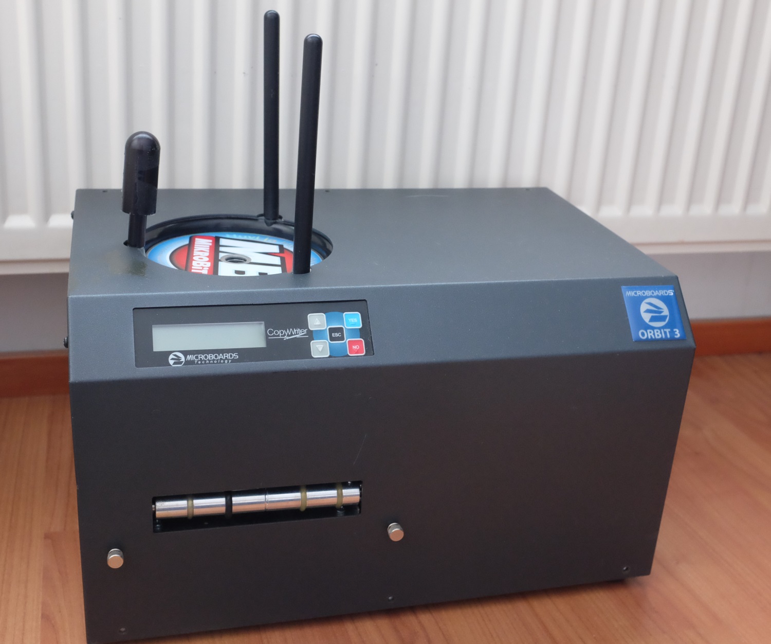
These units weigh about 12 – 15 kg – therefore the shipping from USA was not cheap! The dimensions are 388 x 254 x 241 mm. While the volume may seem big, it does contain three optical drives which take a lot of room.

Without the sheet metal cover.
Serial number sticker.

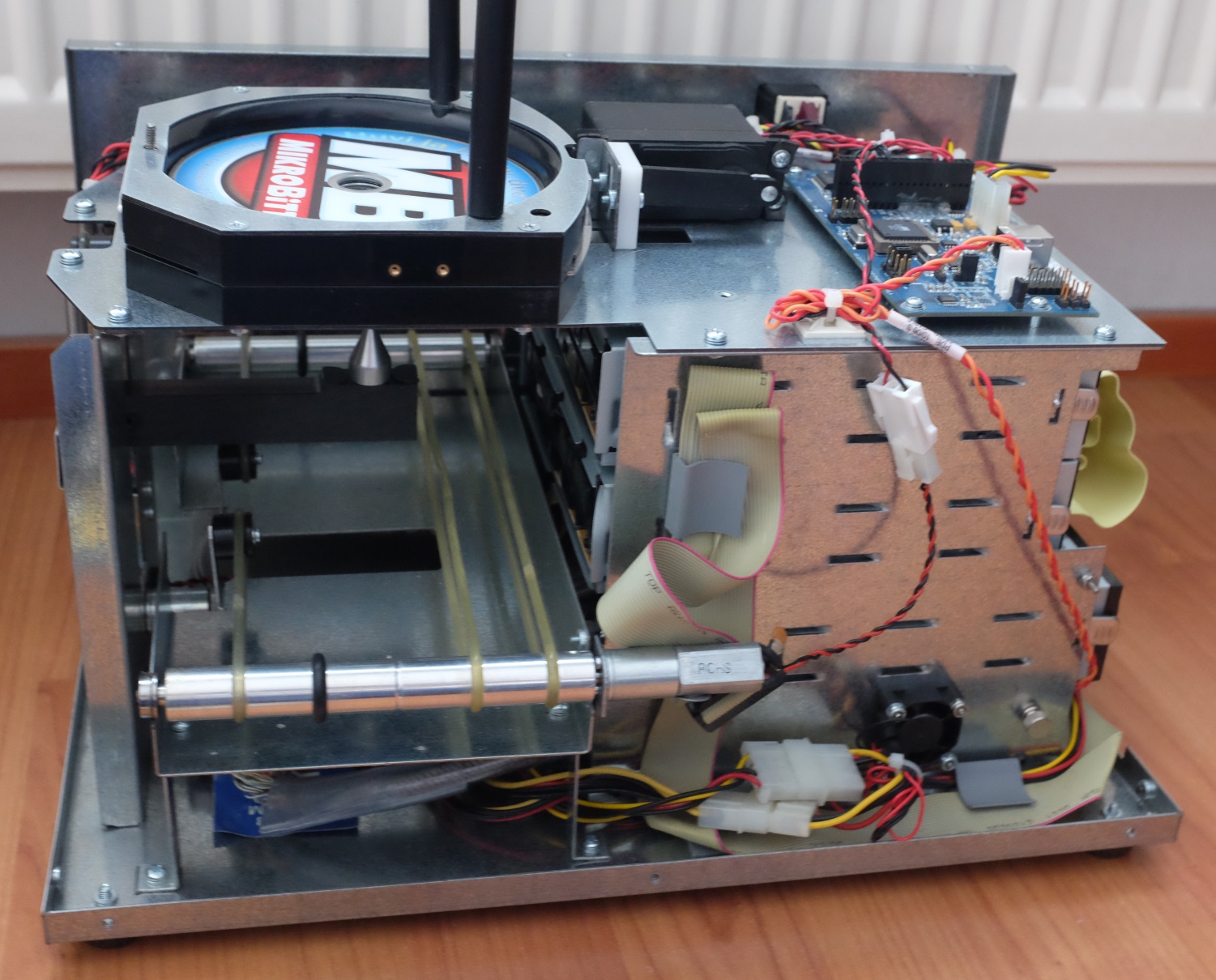
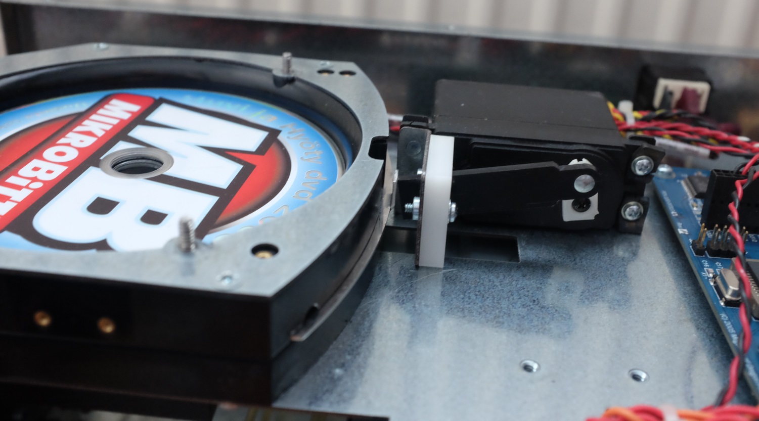
The loader mechanism is based on a big servo which pushes a spring-loaded metal sheet. Basically the metal sheet has a circular opening, which gets aligned with another hole when the servo moves it. The other hole is not perfectly round but has some flanges on the sides, ensuring that only one CD gets loaded per stroke.

Close-up on the loader mechanism.

Underneath there is a spindle which moves up and down on a rail. This moves the CD vertically. The trays of the DVD drives have slots cut in them so that the arm of the spindle can move even when the tray is open. The red and black wires on the left belong to the limit switches of the spindle arm carriage.

Lower part of the loading mechanism with the spindle.

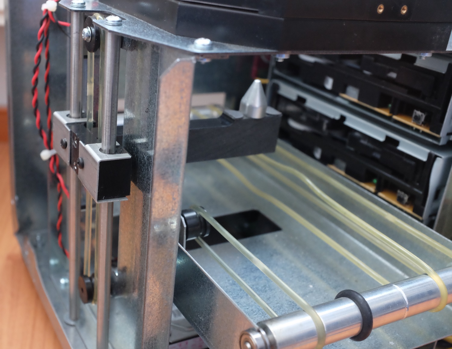
When the CDs have been processed, they go to a conveyor made of polyurethane belt. As the unit is quite old (some parts have a manufacturing date of 2006, others 2009 and 2010) the belts have already gone bad. When the unit was powered on, it would not pass the self-test because the belt of the spindle arm was slipping.

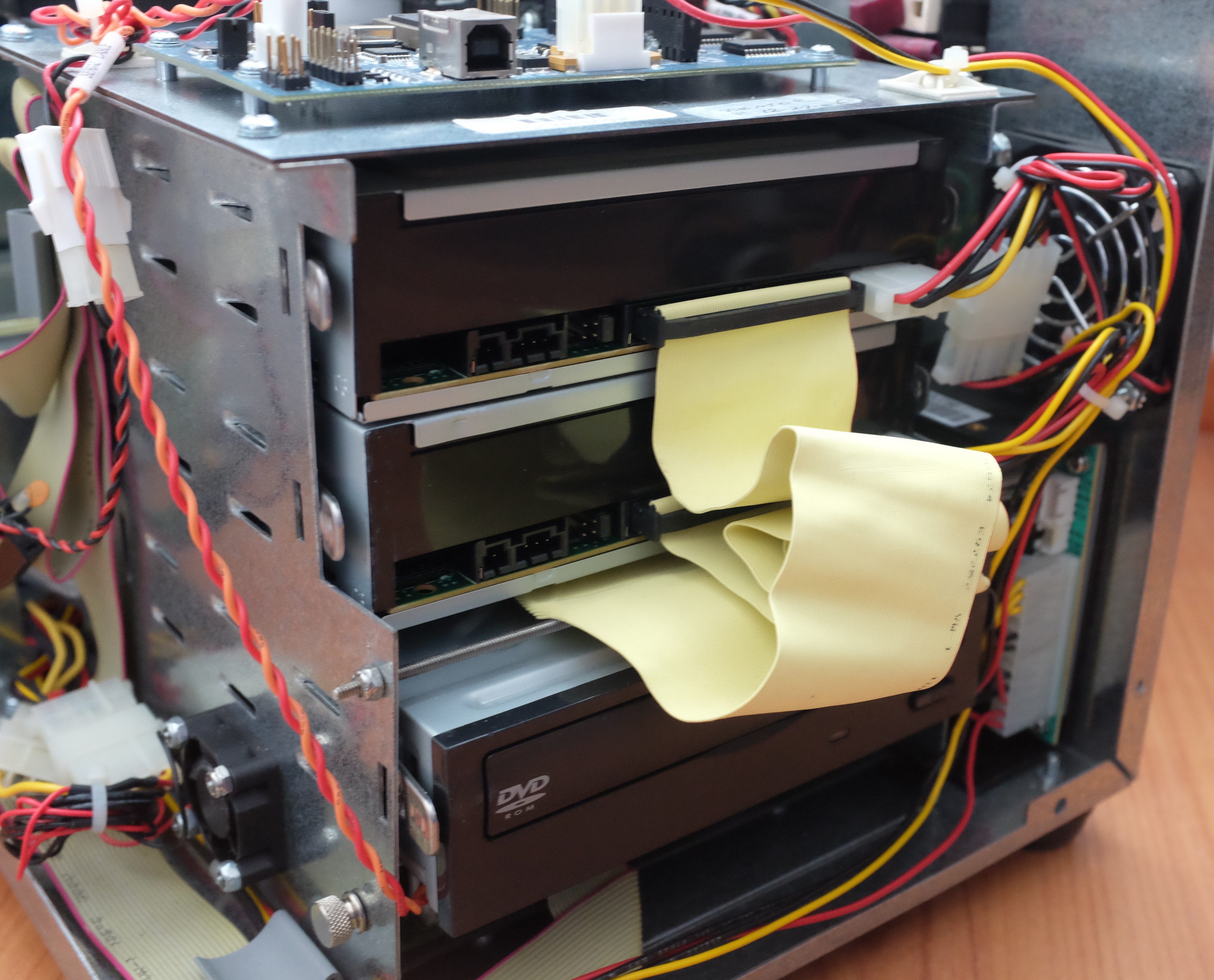
The unit has three IDE drives, two of which can record. The third one can be used to read the master disc which the two other drives write. Obviously using two drives instead of one is faster.

The optical drives.

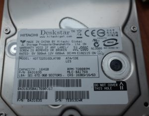
The unit also has a hard drive. According to the manual it can be used for ripping audio CDs.

IDE hard drive.

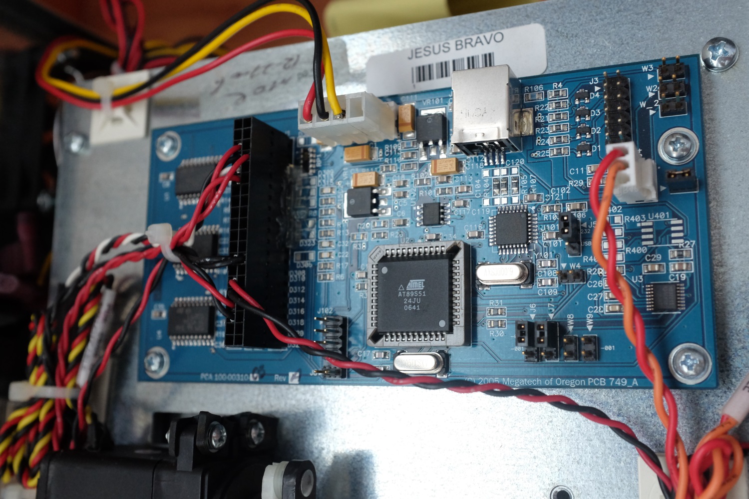
There are two controller boards. One of the boards sits on top of the whole unit, and is used for interfacing to motors and limit switches.

Interface board, connected to motors and limit switches.

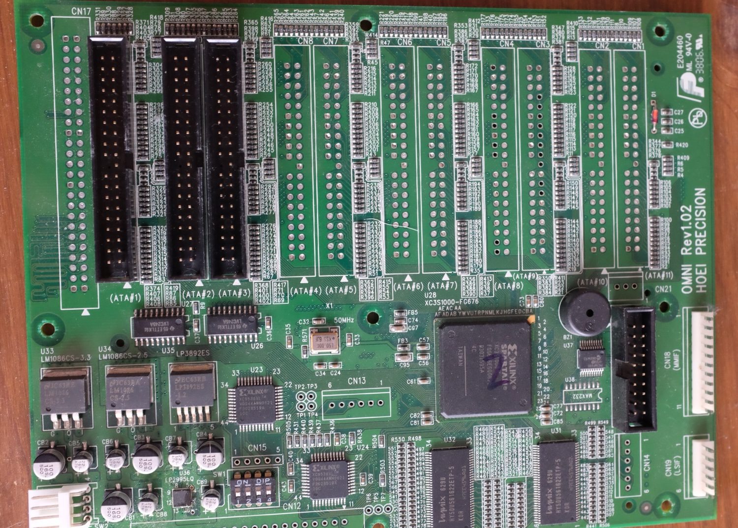
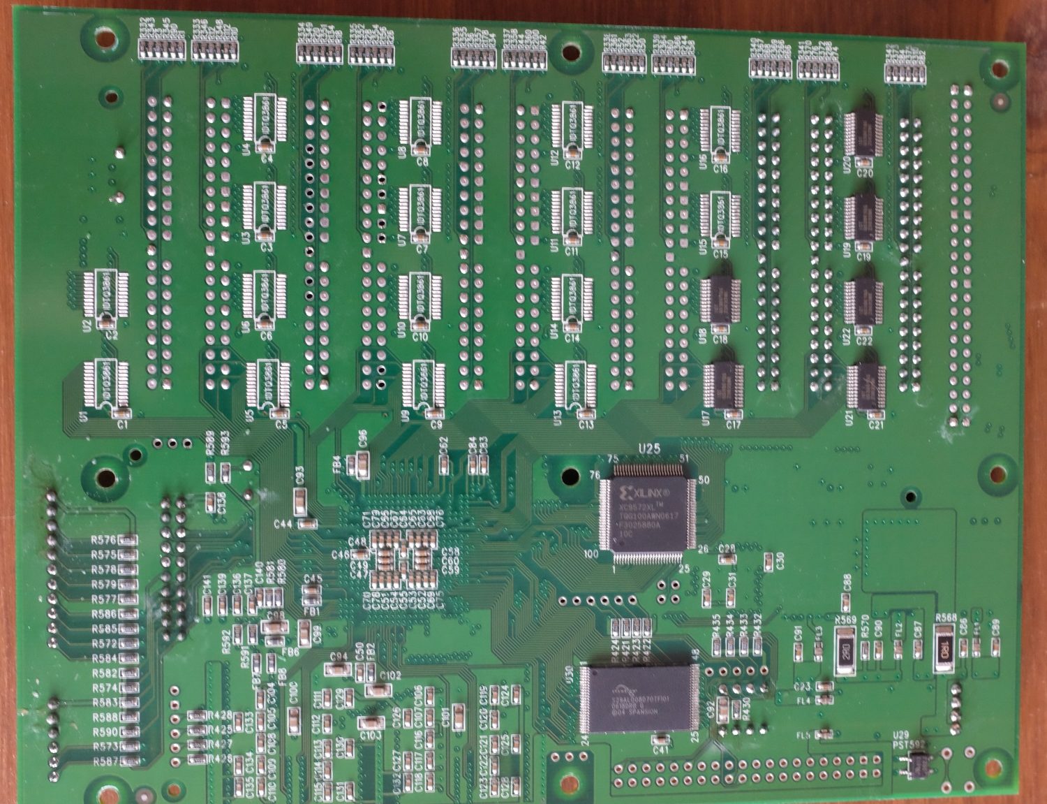
The main board is buried under the optical drives. It boasts a handful of CPLDs and an FPGA.

Location of the main board in the unit.

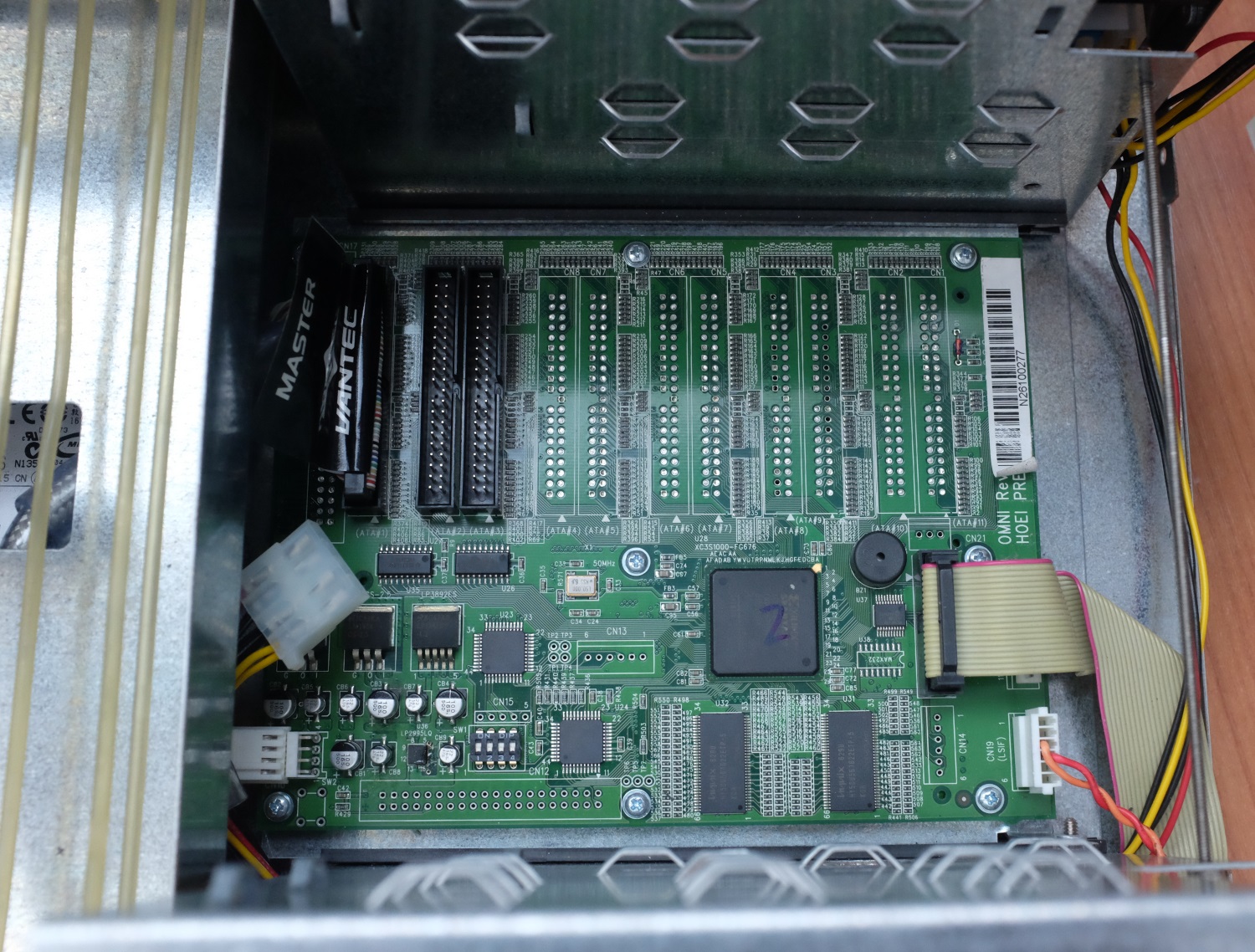
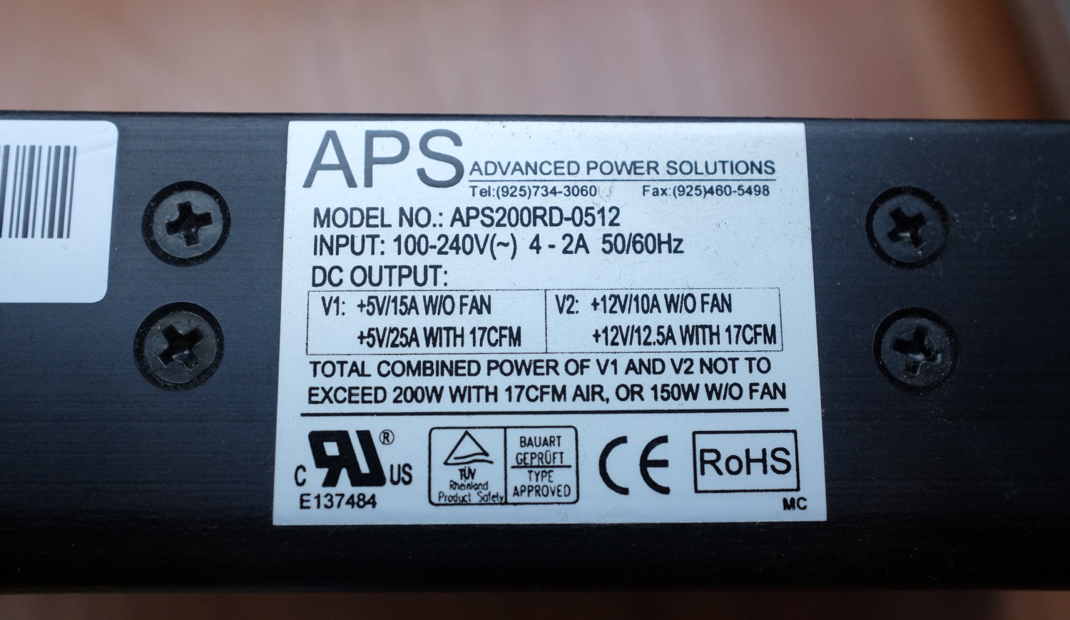
The entire thing is powered by a beefy APS power supply.

Power supply specs.
Power supply.

As I have no use for a device which makes a zillion copies of a CD I am planning to use some of the parts of this unit to create my own ripping station. The brains will get replaced by a modern single-board computer and I will reduce the number of drives to just one. I am also trying to get the volume and the power consumption of the device down.


Building a ferrite core memory, part 2

My ferrite core memory is progressing nicely. I have received the PCB and assembled it for the most parts.

Core memory shield without sense circuit

This evening I tried out how the H bridges worked – after a few tweaks in the Arduino code I was able to get this sequence out:

ferritecore-2
Bit read values from an array of cores.

The only remaining things are to assemble the sense line circuit and to do the final testing and tweaking, which will most likely take a long time.

Building a ferrite core memory, part 1

A while ago I ordered some ferrite cores from Bulgaria in order to build a vintage memory out of them. Yesterday I managed to build a one-bit memory by following what Wayne has done.

Newfile2
Writing 1,0,0 to memory which was in state 0. Enable pulses in yellow, sense line in cyan.

DSC_0064

Now that I have an understanding of the technology and the characteristics of the cores I have I will continue to build a 32-bit version in the form factor of an Arduino shield (my own twist of this project).

Nixie VU meter

Most of my projects seem to deal with lights and music.  VU meters are not fashionable anymore, and the few commercial products I found don’t look too stylish at all. Therefore I decided to build my own using six Soviet IN-9 nixie tubes I had lying around.

The schematic is not too exciting at all. The audio input is connected to a MSGEQ7 graphic equalizer IC which I got from Sparkfun. Its output is processed by an Atmel ATmega88 microcontroller which sends commands to a M62359P DAC. The DAC outputs drive the tubes using a current sink described in “Driving IN-9 Neon Displays” by Dipl.-Ing. Jan Philipp Wüsten. The specific DAC was chosen because it was one of the few 8-channel DACs in DIP package that I could find without spending a fortune on shipping. Nixies are powered by a 1363 power supply. I had to connect a filter to its output (the large Teapo cap + a small resistor) to stop it from whining.

As the nixie tubes require a lot of space, a large enclosure was bought from TME. The mounts in the enclosure were quite far apart so the PCB became quite large. For that reason I etched the PCB myself, which I do quite rarely these days.

For future improvement I could check whether the MSGEQ7 output is linear or logarithmic – I’m thinking it’s linear as the sometimes the readings shoot way up without a great difference in perceived volume. Still, I think that the meter looks great and I’m quite pleased with it.

Testing Amiga DRAM

A friend of mine has an Amiga A500. As usual, the machine was kept in a storage until its retro value was significant, and during those years of storage the battery of the “memory & RTC” expansion had leaked and grown a thick fur on the PCB.

The module didn’t work even after cleaning up the mess. I told I could take a look at it, and sure enough I soon had the module in my hands. As I don’t have an A500 of my own, I decided that the best way to troubleshoot would be to talk to it through the connector, and so I built a testbench out of an Olimex LPC1114 board. The microcontroller has 5V tolerant GPIO pins, which is a bonus.

Amiga DRAM test circuit

It turned out that the microcontroller was quite slow with its bit arithmetics and the debugger on so that the timing didn’t become an issue. After a few hours of debugging with my logic analyzer and fixing a few bad pin choices (eg. mapping an address line to a SWD line) I was finally able to write to each location of one of the chips and read it all back. After repeating it for the other chips I found out that one of the chips was faulty, and the board shall return to its rightful owner after I get a new IC from an eBay surplus store.

Of course, it would have been more elegant to program this thing with Assembly and carefully take note of the timings, but I wrote it in C and made sure that the cycles are not too long. After all, the performance of this device doesn’t matter as testing the chip even with my unoptimized code takes only a few seconds.

Playing music using floppy drives

The Moppy project, which enables an Arduino to use floppy drives to play music, is something a lot of people have tried, but I was not comfortable with installing Netbeans to run the Java app. Instead, I built my own system from scratch.

I used my NXP LPC1768 dev board “LandTiger” for all the complex stuff. It had the MID file in its memory as an array, parsed it and sent the notes over SPI.

A Micronova Mercury FPGA board received the notes and generated the waveforms to play the notes. I used an FPGA so that I could utilize its parallelism for the waveforms and to prevent my VHDL skills from rusting. A neater way would have been to replace the microcontroller with a softcore one inside the FPGA, but I didn’t feel the need as I was just dicking around.

Regrettably, this video is the only piece of evidence I have left. Well, the system consisted of a lot of software and a few wires, so there was nothing much to see.