Hi all,
I was selling this core memory shield it as a kit on Tindie between 2016 – 2022 but it is now discontinued. See Andy Geppert’s Core64 project if you’re interested in getting into core memories, or build your own based on the information on this page.

Here is all the material related to the kit:
- Complete documentation (including BOM & schematics)
- Source code for Arduino program
- Gerber files for manufacturing circuit boards
- For the old version: (2016/2017 PCB date)
Thanks to Ben North and Oliver Nash at corememoryshield.com for the inspiration and encouragement!
This is an amazing retro idea!!!!
Is the CPLD already programmed?
Thanks for your kind words! It is nice to see that there are many people who have an interest in retro technology. I like it because they have the same concepts as modern technology but in a macroscopic and simplified way. To answer your question, yes, I program all the CPLDs prior to shipping.
Thank you for this great kit! I’ve built it and it works very nicely, here is a picture: http://imgur.com/a/UJPHm
So cool to have some self-woven core memory, I learned a lot.
Cheers!
Hi Jussi,
Many thanks for working out this great project. I leave you this picture to show you how it worked out.
https://ibb.co/mh9Gmv
Kind regards,
Hans
Hi Hans,
thank you for the picture. It is a very neat build.
-Jussi
Beautifully made ! Congratulations
It works! Great addition to our museum.
Thanks for reporting back Bob. You have a very interesting museum.
So, you are using big, chunky, cpld which have tons of registers and even more gates as interface to 32bit memory, whoa that waste of hardware is huge.
I wouldn’t call the CPLD big. The interface logic uses 21 of the 32 macrocells available. Compared to a solution with discrete logic chips it is cheaper, more interesting and takes way less space.
I know, but in discrete it would be more like original, this project goal is show vintage memory modules, so it should be as close to original card as possible, other way this project is non sense.
My intention is not to be period accurate but to help people experiment with this technology which is otherwise hard to approach.
I received the kit, but won’t have time to build it until the winter.
I first started to build a core memory in 1971, as a first step toward building my own computer. I strung the first 64x64x1 core plane (https://www.facebook.com/media/set/?set=a.2342844349075926.1073741834.100000511512640&type=1&l=2b708ea9b6), but didn’t get much further after starting university. Thank you for enabling me to get some closure on that project!
Received the kit, assembled it, and it worked the first time. Thanks!
One idea for the future: put holes where the row and column magnet wires terminate on the board so they can be stretched tightly when you’re wiring the array. I tried to get my wires as straight as I could, but I still wasn’t satisfied.
The separate power supply is understandable but annoying. I would love it if you had put a LD1117-3.3 (3.3V Linear Regulator) on the board so it and the Arduino could be powered from a single beefy 5V supply.
Thank you for reporting back. I have plenty of PCBs in stock but I am collecting improvement ideas for the next revision. The holes for stretching the wires are now definitely near the top of the list.
The initial prototype of the shield did have a 5 V to 3.3 V regulator but given the variety of Arduino boards people have sourcing large currents from any rail is problematic. I think the best approach is to have the regulator, a footprint for a connector and a jumper or some circuitry for selection.
As the instructions are a bit outdated, what Arduino board would you recommend for use with the core memory kit?
I recommend Uno R3 as it is pretty cheap and ubiquitous.
By the way, I have not given up maintaining the document. It is just that the product has not changed in a while. If you spot something that raises questions, does not make sense or is out of date then please report.
Thank you! I’ve been programming since the 80’s but this is the first major hardware project I’ve undertaken. I’m sure there’ll be some cussing involved but I’m looking forward to playing with this during my Christmas break. 🤞🙂
Great project!
After the assembly it just started working, without any problems, great job Jussi!
How did I assemble the core without tension holes, etc?
1. Straighten a long enough part of a wire for a vertical line and cut it for a correct length. Solder one end, if needed use a help of tweezers and (what I recommend) kapton tape to hold a wire in place. Do it one by one, or solder all four lines.
Do not use duct tape – it will melt. I recommend using tweezers with very sharp end for maintaining cores – then you can insert tweezers inside a core to grab it firmly, and insert a wire at a same time.
2. Insert 8 cores on each line, and then, again with help of tweezers and kapton tape, solder other end. It should result in 4 nearly perfect straight lines without tension – it will be helpful with next steps.
3. Make a sufficient part of the wire straight, but do not cut it. Holding one end in hand, and using tweezers position cores and insert the horizontal wire one by one (recommend starting from right side, where the board is not limiting access). Then, after making sure that all cores are positioned correctly, place the wire in the exact place, cut it for a correct length and solder both sides.
4. Using rest of the wire put one end through 4 cores, so the end meets lower sense wire pad. Use tweezers, sometimes it is helpful to hold the board upside-down and push cores a little using fingers. Solder it.
5. Put another end according to the drawing. Making curves is a little bit tricky.
6. Done ;)
A few comments/suggestions for new versions:
1. A test point for GND would be useful
2. Additional test points would be nice: for a sense line, and for resistors limiting wire current, so one can attach oscilloscope and see memory in action
3. Maybe an SMD version could be considered? For me it is much easier to solder SMD, than THT and trimming excess legs. Or a combo-version, with SMD pads under THT footprints?
4. A description of which core stores which bit as well as some identification of memory pads (where the wire is soldered) would be nice (to make it easier to identify the current path when reading a schematic.
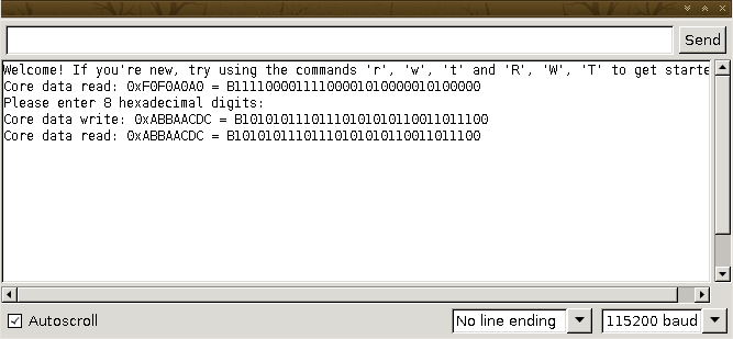
5. An explanation of commands would be handy:
case ‘c’:// pulse core by core (write 0, write 1) until any input
case ‘#’:// prints text in the console until \r reached
case ‘e’:// extended test core by core
case ‘v’:// toggle displaying actions on each core access
case ‘f’:// toggle error reporting in some modes (T mode and corewise test)
case ‘m’:// exchange (read-write) data 120000 times (for time measurement)
case ‘R’:// read word
case ‘s’:// pulse core with address set by A and a commands (write 0, write 0, write 1, write 1)
case ‘a’:// increase core address for pulse
case ‘A’:// decrease core address for pulse
case ‘W’:// write word
case ‘X’:// exchange word
case ‘r’:// read bit
case ‘w’:// write bit
case ‘t’:// test bit-wise
case ‘T’:// test word-wise
case ‘U’:// random test until any input
case ‘z’:// reset error counter
Thank you very much for the assembly tips and improvement ideas Piotr. I would like to address your comments
1. I agree.
2. I agree. I wanted to build the kit in a way that would allow people to experiment with the technology (hence the JTAG headers and the existing test points), but it could be improved.
3. I also think that SMD is easier, and it would definitely allow for some interesting design choices. All the address decoding logic would fit on board as SMD devices. Alternatively the amount of programmable logic chips to choose from would be much larger. However, most people prefer THT so that is what it is going to be.
4. I agree, and I drew a figure which is now in the appendices part of the document.
5. I have though that checking the commands from the source code is good enough but on second thought you do have a point. I will have to do some thinking about rewriting chapter 4.
Hi Jussi,
I’ve completed my kit, its been working all night running tests without errors. Thanks for the great design. David
https://photos.app.goo.gl/dHX3qmmxJQcDuhU28
Thanks for the follow-up and the photos David. I am glad you enjoyed the kit.
Hello “Jussi”!
I would like to know where it is possible to obtain cores for a larger core-memory to build. Do you have a supplier for cores who still does some sort of tiny cores perhaps?
Thank you in advance for any hint to find some larger ammount of those ferite cores in the market.
With my best wishes from Berlin, Germany, Andreas.
The cores in the kit are KWH 5221.3-2113.35; they seem to be still available on eBay.
I’d like to have at least a couple of things about the cores you’ve used:
1- what part number
2- have you observed the magnetization flipping applying, for example, a 50 Hz from an AC transformer providing several Amperes? Here I’m trying with a variety of ferrite toroids (bigger) but nothing appens up to 4 A
I’d like to show the phenomena to students.
Thanks
Fabio
The cores in the kit are KWH 5221.3-2113.35, which seem to be still available in eBay. Can’t remember the exact currents but I am using 0.8 amperes to flip, with 400 mA being a reliable half-current.
There have been quite a few people who have ordered my kit and said that they have used as a part of their lecture; moreover, I know of at least one occasion where the shield has also made it to an engineering text book. You can probe a suitable signal directly for demonstration purposes. Something to keep in mind ;)
I received my kit yesterday, and today it is up and running!
Regarding holes for stretching the wires; I just drilled some small holes at the edge of the board (being careful not to drill into any traces…just the groundplane). That worked great.
I started out powering my Uno from my laptop’s USB port. This seemed to work at first, but I quickly found that bits were getting reset to zero. I went and found a 9V wall wart (1 amp) and that fixed everything. But it seemed that reading and writing 1 bit at a time worked okay from the USB power, but using the ‘R’ and ‘W’ commands or the ‘T’ and ‘t’ commands failed. It occurred to me that on USB power, slowing things down a bit would work better. Changing WRITE_OFF_US from 10 to 100 microseconds made the shield completely reliable on USB power alone.
This has been great fun. Back 50 years ago I got some 80×40 core planes from a local junkyard (where IBM junked old card readers) and did a high-school science fair project getting them to work. It was great fun then and this was really a trip down memory lane (pun intended).
Thanks for a great kit.
Thanks for wiring back, Mike. I am glad you enjoyed the kit and were able to solve the issues with power supply.
I received the kit. Thanks for sending it so quick…. now wish me luck. This is my first project like this!
Hi Larry, thanks for writing back. Nice to hear that the postal service has resumed normal operations. Good luck!
Any tips on theading the wires through the cores? I managed to break 1 of the 4 longer wires as I was trying to do the cross wires. I think i have enough wire to redo, but have ordered some extra just in case (btw thanks for including the extra cores in the kit). I noticed the wires were tight at first but then stretched also. Anyway, im really a novice and happy to make progress but any tips appreciated.
First of all, make sure to read the tips from the documentation. Start with the long wires and thread them through eight beads. For the shorter wires I recommend cutting a piece of wire, threading it through the cores using and soldering once that is done. For the sense line you probably want to start at the midpoint.
At all stages you probably want to use tweezers to pull the wire.
Finally I built the kit (2017-01-12 version) that I got as a gift already years ago.
I am impressed how neatly some others did weave in the wires into the core matrix. I tried my best and it looks decent, but not quite as perfect as I have seen it on pictures of some others.
The shield draws excessive current when powered with 3.3V but not connected to the Arduino because the inputs are open and thus “weakly pulled up” as the ispMACH 4A Family datasheet for the CPLD says. Thus, the ENABLE is always asserted and a row and a column current (both in the order of 300mA) are constantly flowing. I bodged in a suited pull down resistor at pin 2 of the CPLD (the ENABLE input) which resolved this.
I also adapted the program to work with the Arduino Leonardo.
The core memory shield worked immediately as expected as soon the Arduino issues were resolved.
This was a nice opportunity to revive my HW and SW skills and I really enjoyed it.
I have just seen your project it is simply marvelous , I am going to show how it works to a few boys who are learning the beginning of electronics.
From Spain great Job .
Muchas Gracias
Luis