Over the holidays I had once again the pleasure of tinkering with my friend’s Amiga 500. This time helped him with flashing the HxC firmware to his Gotek floppy drive emulator which he had mounted in an external drive case. The flashing went smoothly, but in order to be able to boot from the Gotek device the Amiga needed a hardware modification.

This came as no surprise as we had done our homework. There are multiple products in the market but I did not really like them as they connected the IC pins to a DPDT switch with a long wire in order to swap the signals in pins 13 and 14. The CIA ICs are getting rare, and although unlikely, killing one with ESD would ruin the day. Moreover, the required switch type greatly limits the selection of switches and mounting methods one can use to make the solution as neat as possible. The prices of the existing solutions are also quite high if you consider the shipping costs as well.
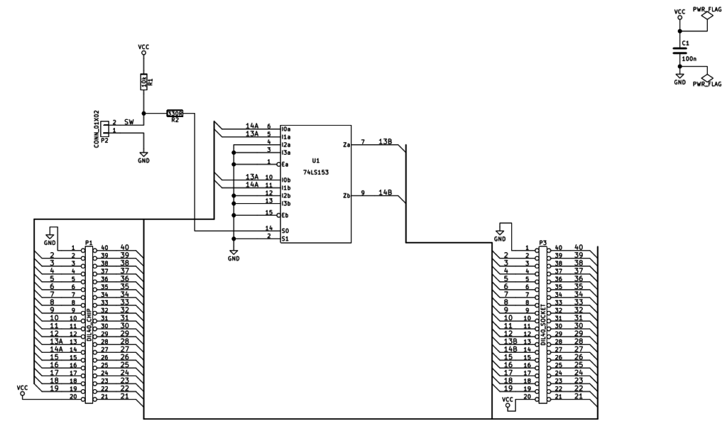
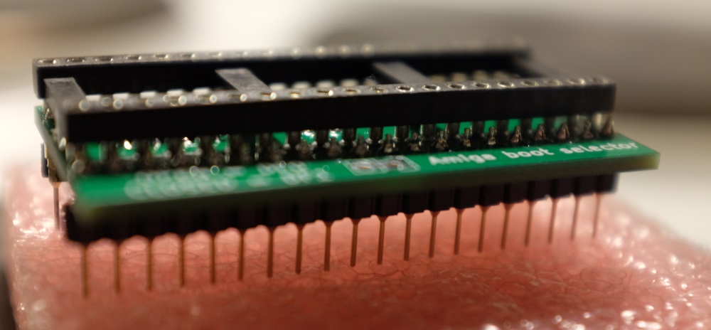
For those reasons I created my own design. It is a really simple solution which uses a 74HC153 multiplexer to do the switching. The top side of the board has a precision DIP socket for the even CIA. The bottom part has the turned male pins for plugging the whole thing to the original IC socket. The circuit will draw its power (approx. 2 mA) from voltage supply of the CIA chip.
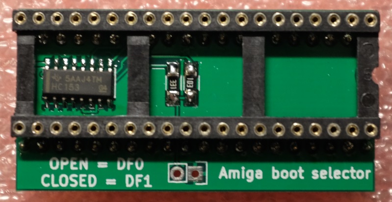
You can build your own Amiga Boot Selector by using these Gerber files amiga_df0_df1.zip. The project is licensed with a CC BY 4.0 license.

Hi Jussi, do you intend to make any more? I like you thinking about the problems with the popular ones.
Hi Sean, thanks for your comment. I think I won’t carry the product anymore, but I added the gerber files for the PCB to the blog post so that you can build your own.
Thank you!
Hello Jussi ;)
Thankl you for your project but tell me about used all elements as resistors etc..and which is best program to open your GBR files and print it onto laser printer to make own pcb with thermo transfer methode ? thx.
Hi Paul, the resistors and capacitors do not have to be anything special, just about anything in 1206 form factor will work. For the connectors I recommend the ones which have turned pins.
I am afraid I can’t really help with the question about the PCB. I stopped making my own boards when the Chinese boards became stupidly cheap. For example, this board can be manufactured for less than $10 – just not worth the time to manufacture your own (the layout is also not optimized for that). You can use http://pcbshopper.com/ for comparing the prices of PCB manufacturers.
Correct me if I’m wrong, but don’t you still need a switch to do this? you’re just using the 74ls153 to buffer the switching to save the CIA chip?
Yes, one still needs a single pole
momentarylatching on/off switch (not a dpdt one though).Also, is there any change you can also share the design files (I assume they’re from Eagle)?
This has been designed in KiCad. I see no point in sharing the files as the schematic and the gerbers are already available and the design is very simple.
Understood.
What package is the 74hc153 then? TSSOP, SO, or SOIC?
And are the df0/df1 jumper pins a 2.54mm pitch?
Thanks
The package is narrow SOIC and the pitch is 2.54 mm.
Thanks for freely releasing this – you are a champ :)
dear jussi, i tried to upload the gerber files to an pcb manufacturer, but it says that the zip file does not contain any drill files ?! can you help me here ?? do you have the drill files or file ? thanks in advance !
Hi, the drill file in the zip has .txt extension. Some manufacturers want to have a file with .drl extension but the contents are the same so you can just rename.
Hi, Thanks for your help. i just renamed but now it says “I can’t find a board outline file.” . :) is that something special ?
The outline is defined in amiga_df0_df1-Edge.Cuts.gml. Read the manufacturer FAQ for their file name extension / format.
Dear Jussi, thanks for all your help and time !!
Hello!
I got a print and components and needs to solder myself. Just wonder if you have a layout for placing the R1, R2 and C1 on the print.
Hi, if you orient the board so that the notch is on top, the passive components are then from top to bottom R1, R2, C1.
Hi Jussi,
I build one of your circuit, but i ran in to Problems.
there are no Solderbridges at all, but i used al 74HC153D instet the LS Version. Is this a Problem maybe?
Hi HyBird, 74HC153 is fine so the problem is somewhere else.
Hi Jussi,
It looks like a 2 bit controlled inverter. Is there any reason to not use simple XOR or XNOR gates (like 74LS86 or 74LS266) instead of a mux? The circuit would be even simpler.
Nice design though
This was quite directly inspired by the boot selectors which use DPDT switches so the circuit topology follows those quite closely. Surely it could be implemented using other gates as well, but I reckon it is already pretty cheap as it only uses a single chip.
Thank you. I guess it can be doable using only two XOR gates (and keeping your pull up/down switch).
Another thing I’m strugling to fully understand (not related to your design but in general) is why the internal FDD doesn’t work when sel0 is redirected to the external FDD and sel1 to the internal FDD. My feeling is it has something to do whith _MTR0 and _MTRX signals from the GARY chip (pins 46 and 47).
Did you made some researches or experiments on that?